

Appearance
Quantum Error Correction with lightrider
An introduction to running circuit-level QEC experiments with the lightrider SDK: building encoded circuits for several stabilizer codes, injecting noise, simulating on the local stabilizer backend, and decoding with PyMatching to measure logical fidelity before and after correction.
Installation
bash
pip install lightrider pymatchingpymatching is required for the MWPM decoding used by build_matching() and logical_fidelity().
The QEC test workflow
Every code class follows the same five-step pattern:
python
from lightrider import RotatedSurface_Code, inject_sc_noise, draw_circuit, get_backend1. Build the code and its QEC-test circuit (prepare logical |0>, run syndrome rounds, measure all data qubits):
python
RScode = RotatedSurface_Code(distance=3, rounds=1)
RScirc = RScode.build_circuit_QECtest()
2. Inject circuit-level Pauli noise at physical error rate p:
python
p = 1e-4
noisy_RScirc = inject_sc_noise(RScirc, p=p)
3. (Optional) visualize the circuit:
python
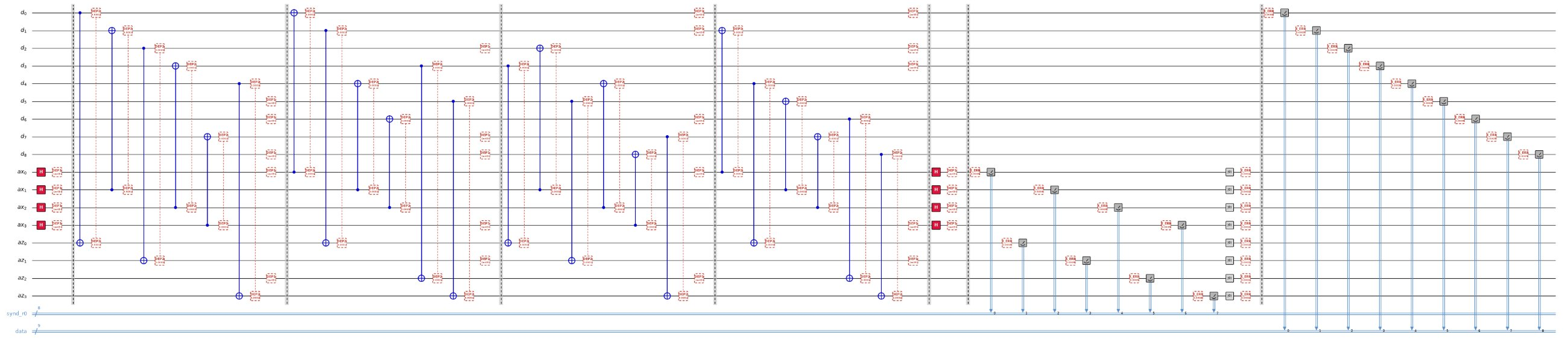
draw_circuit(noisy_RScirc.to_text(), save_path="out.png")Example result (d=3 rotated surface code, 1 round):
4. Simulate on the local stabilizer backend:
python
result = get_backend('stabilizer').run(noisy_RScirc, shots=20000).result()
shots = RScode.counts_to_shots(result.counts)
5. Decode and compare logical fidelity with and without correction:
python
res = RScode.logical_fidelity(shots, 'Z', p=p)   # MWPM via pymatching
print(f"Raw Fidelity: {res['fidelity_before']:.6f} (err {res['error_before']:.2e})")
print(f"QEC Fidelity: {res['fidelity_after']:.6f} (err {res['error_after']:.2e})")
Typical output (d=3 rotated surface code, p=1e-4, 20k shots):
Raw Fidelity: 0.997250 (err 2.75e-03)
QEC Fidelity: 0.998800 (err 1.20e-03)
logical_fidelity() returns a dict with fidelity_before / error_before (raw logical readout, no decoding) and fidelity_after / error_after (after XORing in the decoder's predicted logical flip). "Fidelity" here is the logical bit fidelity, 1 - logical error rate.
Available codes
Rotated surface code
Advantages: the field's workhorse — only weight-4 (bulk) and weight-2 (boundary) checks on a square lattice, the highest known error threshold among practical codes, and a mature MWPM decoder that runs in near-linear time.
python
from lightrider import RotatedSurface_Code

RScode = RotatedSurface_Code(distance=3, rounds=1)
res = RScode.logical_fidelity(shots, 'Z', p=p)    # basis: 'Z' or 'X'
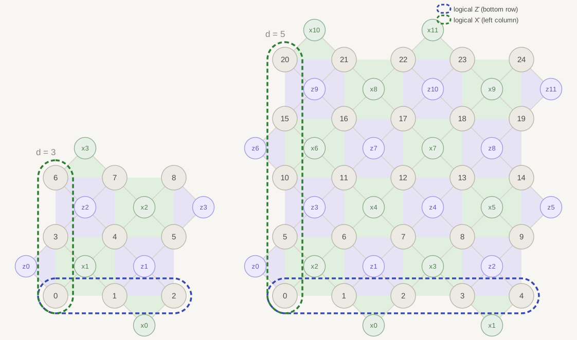
[[d^2, 1, d]]: logical Z is the bottom row (d qubits) and logical X is the left column (d qubits) — marked in the figure below by the blue and green dashed loops, overlapping at qubit 0; the small green/purple dots between data qubits are the weight-4 (bulk) and weight-2 (boundary) X- and Z-stabilizers, with each one's light green/purple fill showing exactly which qubits it checks (a square in the bulk, a triangle poking outward at the boundary).
Decoded with MWPM on the multi-round matching graph; a virtual final round is reconstructed from the data-qubit readout (the standard boundary trick for memory experiments).
Repetition code
Advantages: minimal — only nearest-neighbor weight-2 checks and 1D connectivity, making it the cheapest possible sanity check for a new device or noise model before moving to a real 2D code.
python
from lightrider import Repetition_Code

Repcode = Repetition_Code(n=3, rounds=1)
res = Repcode.logical_fidelity(shots, p=p)
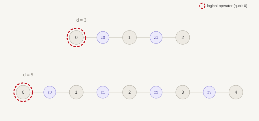
[[n, 1, n]]: the logical qubit is a single data qubit (index 0, circled in the figure) — under the ZZ stabilizer group (the purple z dots between neighbors) every physical Z_i is equivalent to logical Z-bar, so any one qubit's readout already carries the encoded value when no errors occur.
Bit-flip repetition code — the simplest matchable code, useful as a sanity check.
Five-qubit code
Advantages: the smallest possible code protecting against an arbitrary single-qubit error — useful whenever qubit count is the bottleneck and full 2D-lattice overhead isn't affordable.
python
from lightrider import FiveQubit_Code

FQcode = FiveQubit_Code(rounds=1)
res = FQcode.logical_fidelity(shots, expected=0)
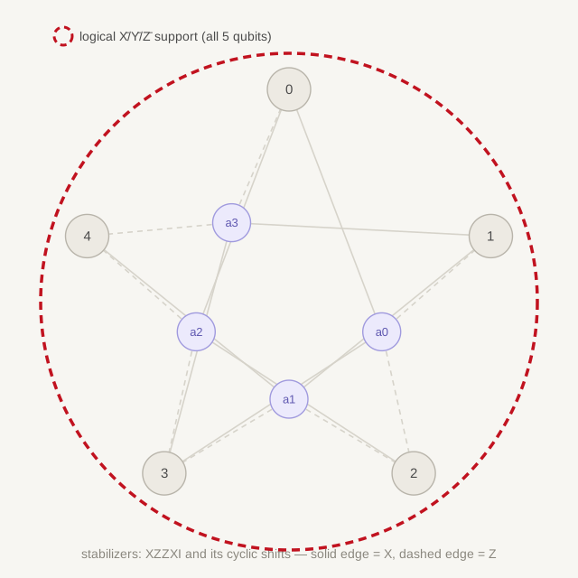
[[5, 1, 3]]: logical X, Y, and Z each act on all 5 data qubits, circled together by the single red loop in the figure; the 4 ancillas (a0-a3) each realize a weight-4 stabilizer mixing X, Y, and Z across different qubits (solid edge = X, dashed edge = Z, per the caption).
The perfect [[5,1,3]] code. Its errors flip more than two stabilizers, so it is not decodable by plain matching — decoding is handled internally (no p/matching argument).
6-6-6 color code
Advantages: transversal implementation of the full Clifford group (H, S, and CNOT all bias-free), unlike the surface code, which needs lattice surgery or magic-state tricks for non-Clifford/S gates — valuable when logical gate overhead matters more than physical qubit count.
python
from lightrider import Color_Code

Colcode = Color_Code(distance=3, rounds=1)
res = Colcode.logical_fidelity(shots, p=p)
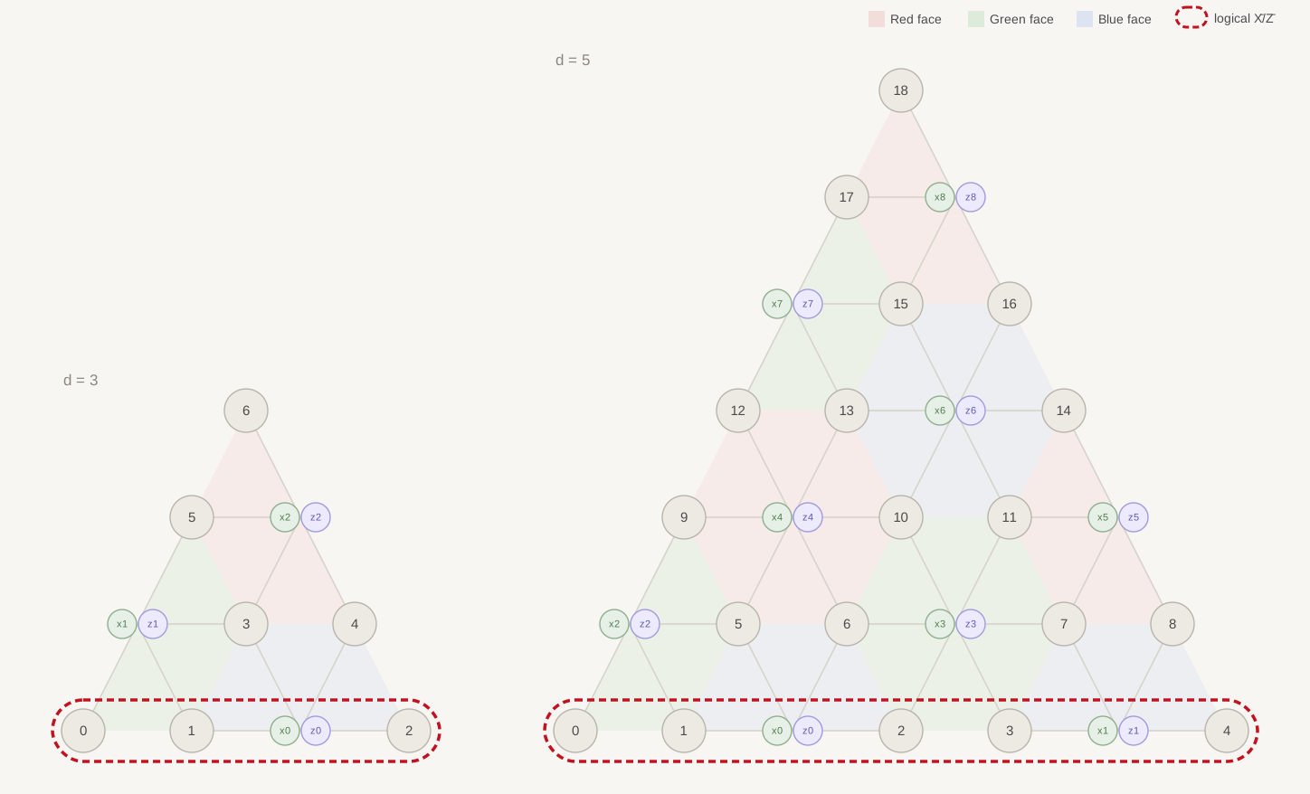
[[(3d^2+1)/4, 1, d]]: logical X and Z (self-dual, so they share support; logical Y is their product) sit on the boundary row of d qubits circled by the red dashed loop. Each face is one stabilizer, shown as a light red/green/blue tile per the 3-coloring, with its x/z ancilla dots marking the X- and Z-type check sharing that face's qubit support.
Triangular 6-6-6 color code, decoded with a restriction decoder: three color-restricted matching subgraphs whose corrections are combined. Note the round-count constraint — fidelity readout needs a deterministic logical-Z observable, which occurs when rounds % 3 == 2 (rounds = 2, 5, 8, ...; at least one Z-type syndrome round is also needed, so rounds >= 5 in practice).
Only distance=3 is available on real QPU hardware (with 4 connections per qubit); distance > 3 (e.g. d=5) can only be run on the local 'stabilizer' simulator backend.
Building custom circuits (logical gates between rounds)
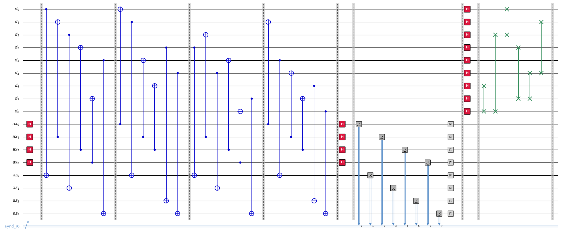
Instead of build_circuit_QECtest(), you can assemble the circuit round by round and insert logical operations, e.g. a transversal logical Hadamard between two blocks of syndrome extraction:
python
RScodeH = RotatedSurface_Code(distance=3, rounds=1)
RScodeH.circ = lightrider.Circuit(RScodeH.total_qubits, RScodeH.total_clbits, name="surf_test")
for i in range(1):
    RScodeH.syndrome_round(i)
RScodeH.logical_H()
draw_circuit(RScodeH.circ.to_text(), save_path="RS_LH.png")
Example result (d=3 rotated surface code, 1 round, followed by a transversal logical H):
Available logical gates:
| Logical gate | Effect |
|---|---|
logical_X() | Transversal logical Pauli-X: flips the encoded qubit's Z-basis readout, applied as physical x gates across the logical-X operator's support. |
logical_Y() | Transversal logical Pauli-Y: composition of logical_X() and logical_Z(); flips the readout in both bases. |
logical_Z() | Transversal logical Pauli-Z: flips the encoded qubit's X-basis readout, applied as physical z gates across the logical-Z operator's support. |
logical_H() | Transversal logical Hadamard: swaps the roles of the X and Z stabilizers, and of the logical X/Z operators. |
logical_S() | Logical phase gate: maps the logical X operator to Y (and Y to −X). Not transversal for CSS codes like the surface code — currently only implemented for the repetition code, as decode → single physical s → re-encode. |
logical_X() / logical_Y() / logical_Z() / logical_H() are transversal (one physical gate per qubit in the relevant operator's support) and are tracked by the class so logical_support() stays correct afterward. logical_H() is the odd one out among these four — it also swaps which physical stabilizers are "X-type" and "Z-type" for every later round, whereas the Pauli gates leave the stabilizer frame unchanged. Because the decoder helpers assume a single stabilizer frame across all rounds, decoding a history that spans a logical_H() call needs separate treatment for the rounds before and after the swap.
logical_S() has no transversal implementation on CSS codes (the S gate is not a stabilizer automorphism for the surface or color code), so it is currently only supported for the repetition code, where it is realized by decoding to the logical qubit, applying a single physical s, then re-encoding — not a fault-tolerant transversal operation.
Using a different decoder
build_matching() / logical_fidelity() are PyMatching-specific conveniences. To plug in any other decoder (fusion-blossom, BP-OSD, a custom matcher), export the decoding problem as plain matrices:
python
problem = RScode.decoding_problem('Z', p=p)
problem['check_matrix']        # (num_detectors x num_faults) sparse GF(2) matrix
problem['observable_matrix']   # (1 x num_faults): which faults flip the logical
problem['weights']             # log((1-p)/p) edge weights
problem['num_detectors'], problem['num_rounds']
Per-shot detector vectors to feed such a decoder come from:
python
dets = RScode.extract_detectors(single_shot_clbits, 'Z')Detectors are XORs of consecutive syndrome rounds (plus the virtual final round for 'Z'), so they fire only when an error occurs — the right input for any syndrome decoder.
Practical tips
- Restart your kernel after (re)installing the package; imports are cached per session.
- At low
pthe error rates are small — 20k shots gives only a handful of error events. Use 1e5–1e6 shots (or a largerp) for statistically meaningful before/after comparisons. - Expect
error_afterwell belowerror_beforefor matchable codes at lowp; if they're equal, check thatshots, the matching, and the code instance all come from the samedistance/roundsconfiguration. - All simulation here runs locally on the
'stabilizer'backend (Clifford-only, scales to hundreds of qubits). The same circuits can be submitted to IQM hardware viaget_backend('iqm', ...).